


|
|
Register To Post |

| Matatk | Ever seen the inside of a blower control module? | ||
|
Webmaster
 
|
So...have you ever seen the inside of a blower control module? I hadn't and I was curious so I decided to cut this one open (the dead one from my recent a/c repair). I was wondering if it might give a sign or symptom as to the reason it failed.
I cut it open with a dremel and noticed the whole board was covered with about 1/4" of this clear, gooey silicon kind of gel that reminded me of contact cement. I don't know if it keeps to board cooler (these things get HOT) or if it's to keep moisture away from the board. Regardless, it's really sticky and hard to get off the board. As far as the board itself, I don't even know what I'm looking at....lol. I thought there might be some telltale signs of bad solder, arcing, etc. I didn't find anything like that, so there's no way for me to visually tell what part went bad (ie, a simple resistor to replace). Most parts on the board didn't have visible numbers, the little blue tabs did but I didn't copy them down. So anyway, here's what it looks like: 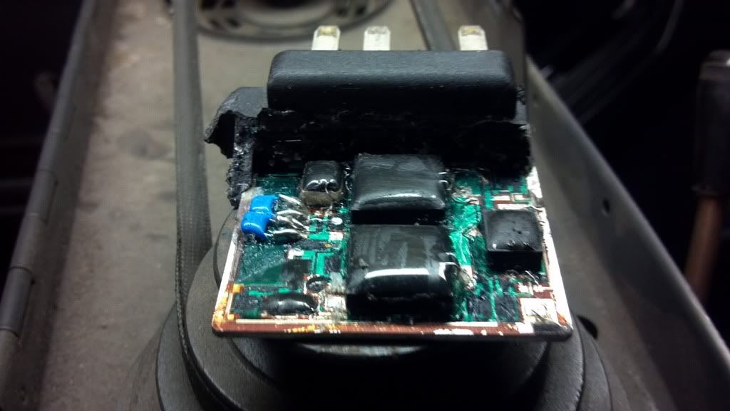 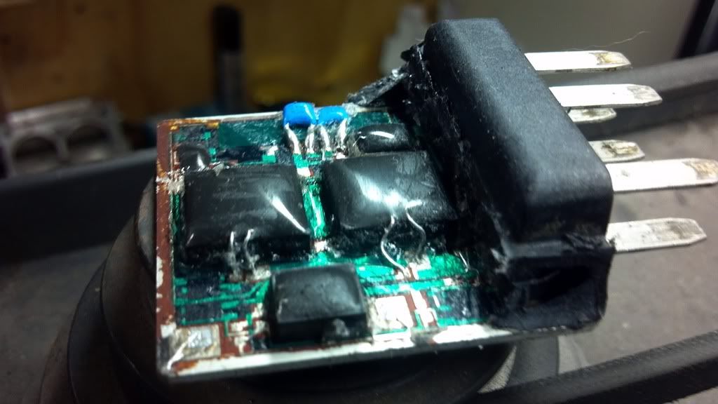 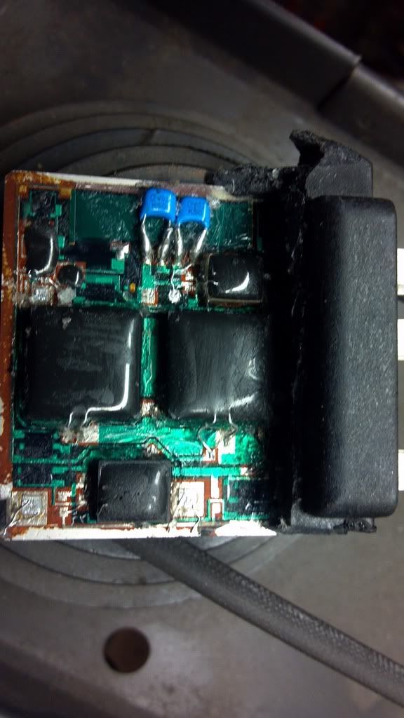 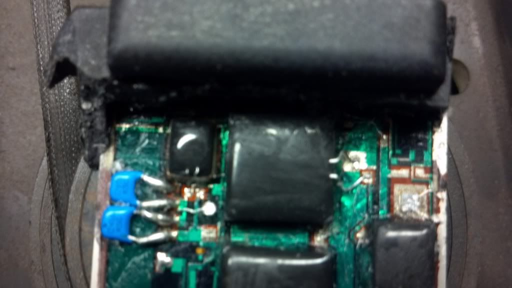 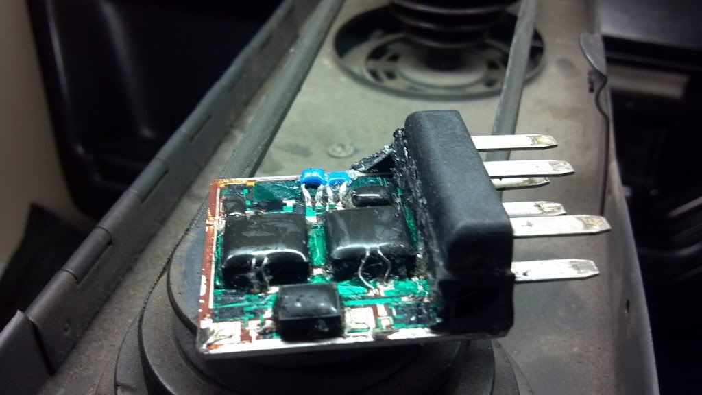 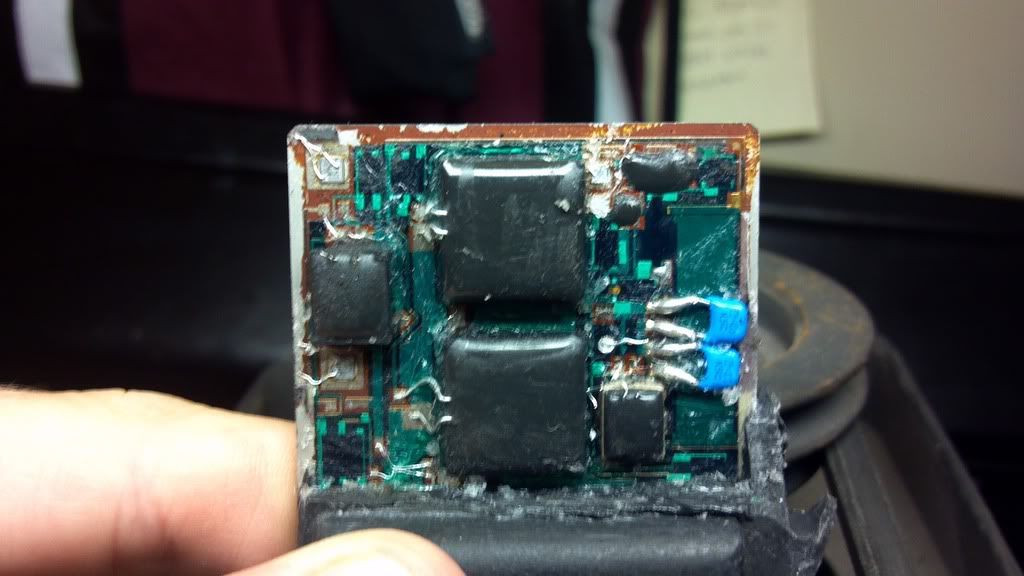 |
||
Posted on: 2012/7/26 13:04
Edited by Matatk on 2012/7/26 18:44:47 Edited by Matatk on 2012/7/26 18:45:21 |
|||
|
_________________
2002 EBM convertible, Magnusson supercharger, cam, headers, etc. 1989 Corvette...RIP |
|||
 Transfer Transfer
|
 
|
||

| Durango_Boy | Re: Ever seen the inside of a blower control module? | ||
|
Elite Guru
 
|
Drill presses make good props for taking pic s of parts. LOL.
I like the older modules that have rheostats and are more mechanical than electronic. |
||
Posted on: 2012/7/26 13:56
|
|||
|
Transfer
|
|
||
| Matatk | Re: Ever seen the inside of a blower control module? | ||
|
Webmaster
|
Yeah, the drill press happened to be sitting on the work bench...so it became a platform
 |
||
Posted on: 2012/7/26 14:26
|
|||
|
_________________
2002 EBM convertible, Magnusson supercharger, cam, headers, etc. 1989 Corvette...RIP |
|||
|
Transfer
|
|
||
| TommyT-Bone | Re: Ever seen the inside of a blower control module? | ||
|
Chair-man of the bored
 
|
If the pics were just a little bit bigger I'd be able to see it in more detail. |
||
Posted on: 2012/7/26 15:59
|
|||
|
Transfer
|
|
||
| bogus | Re: Ever seen the inside of a blower control module? | ||
|
Grand Imperial Pooh-Bah
 
|
lets see.. it is a solid state device... controlling current flow... so it will get hot.
that's why they have that big aluminum thing on it. and why it is in the air box. As for bits... the blue things are capacitors... the black things are mosfets of some sort. my guess? a fet or fets failed. They die over time. the goo? it's a moisture barrier... |
||
Posted on: 2012/7/26 18:04
|
|||
|
_________________
The single biggest problem with communication is the illusion that it has taken place. - George Bernard Shaw Education is the best tool to overcome irrational fear. - me |
|||
|
Transfer
|
|
||
| Matatk | Re: Ever seen the inside of a blower control module? | ||
|
Webmaster
|
Quote:
They are big so you CAN see detail..and so you can see them without your glasses, Tommy But the site should resize them automatically and they should be clickable for a larger size. Don't know why it's not working.Matthew |
||
Posted on: 2012/7/26 18:40
|
|||
|
_________________
2002 EBM convertible, Magnusson supercharger, cam, headers, etc. 1989 Corvette...RIP |
|||
|
Transfer
|
|
||
| Matatk | Re: Ever seen the inside of a blower control module? | ||
|
Webmaster
|
I changed the image tags, that should help with the pictures being too big.
|
||
Posted on: 2012/7/26 18:46
|
|||
|
_________________
2002 EBM convertible, Magnusson supercharger, cam, headers, etc. 1989 Corvette...RIP |
|||
|
Transfer
|
|
||
| Matatk | Re: Ever seen the inside of a blower control module? | ||
|
Webmaster
|
Quote:
Good explanation, Andy. "The metal–oxide–semiconductor field-effect transistor (MOSFET, MOS-FET, or MOS FET) is a transistor used for amplifying or switching electronic signals. Although the MOSFET is a four-terminal device with source (S), gate (G), drain (D), and body (B) terminals,[1] the body (or substrate) of the MOSFET often is connected to the source terminal, making it a three-terminal device like other field-effect transistors. Because these two terminals are normally connected to each other (short-circuited) internally, only three terminals appear in electrical diagrams. The MOSFET is by far the most common transistor in both digital and analog circuits, though the bipolar junction transistor was at one time much more common." |
||
Posted on: 2012/7/26 18:47
|
|||
|
_________________
2002 EBM convertible, Magnusson supercharger, cam, headers, etc. 1989 Corvette...RIP |
|||
|
Transfer
|
|
||
| BillH | Re: Ever seen the inside of a blower control module? | ||
|
The Stig Moderator
 
|
Yuck, the stuff I had to look at all the time when I was working.
|
||
Posted on: 2012/7/27 2:41
|
|||
|
_________________
Every man dies but not every man lives. |
|||
|
Transfer
|
|
||
| BillH | Re: Ever seen the inside of a blower control module? | ||
|
The Stig Moderator
|
Quote:
Very Good. Now explain propagation delay in a circuit. |
||
Posted on: 2012/7/27 2:43
|
|||
|
_________________
Every man dies but not every man lives. |
|||
|
Transfer
|
|
||
| Scott7 | Re: Ever seen the inside of a blower control module? | ||
|
Senior Guru
 
|
Quote:
"propagation delay is the length of time starting from the point that the input to a logic gate becomes stable and valid, to the time that the output of that logic gate is stable and valid. Often this refers to the time required for the output to reach from 10% to 90% of its final output level when the input changes. Reducing gate delays in digital circuits allows them to process data at a faster rate and improve overall performance." How's that? |
||
Posted on: 2012/9/26 21:02
|
|||
|
Transfer
|
|
||
| BillH | Re: Ever seen the inside of a blower control module? | ||
|
The Stig Moderator
|
Quote:
Perfect, maybe that's why the feet on the chip carriers I usta sell kept getting smaller and smaller.  |
||
Posted on: 2012/9/26 23:55
|
|||
|
_________________
Every man dies but not every man lives. |
|||
|
Transfer
|
|
||
| Matatk | Re: Ever seen the inside of a blower control module? | ||
|
Webmaster
|
Quote:
Shoes were too expensive, so they figured the smaller the feet, the smaller the shoe, the smaller the cost. |
||
Posted on: 2012/9/27 22:25
|
|||
|
_________________
2002 EBM convertible, Magnusson supercharger, cam, headers, etc. 1989 Corvette...RIP |
|||
|
Transfer
|
|
||
| BillH | Re: Ever seen the inside of a blower control module? | ||
|
The Stig Moderator
|
Quote:
The way I heard it was: The smaller the feet, the smaller the........nevermind. |
||
Posted on: 2012/9/27 22:36
|
|||
|
_________________
Every man dies but not every man lives. |
|||
|
Transfer
|
|
||
| Matatk | Re: Ever seen the inside of a blower control module? | ||
|
Webmaster
|
Quote:
footprint. |
||
Posted on: 2012/9/27 22:39
|
|||
|
_________________
2002 EBM convertible, Magnusson supercharger, cam, headers, etc. 1989 Corvette...RIP |
|||
|
Transfer
|
|
||
You can view topic.
You cannot start a new topic.
You cannot reply to posts.
You cannot edit your posts.
You cannot delete your posts.
You cannot add new polls.
You cannot vote in polls.
You cannot attach files to posts.
You cannot post without approval.
|
|