


|
|
|
|
|
Register To Post |

| bigmoe | 30 dollar 12HP+ air foil? | ||
|
Senior Guru
 
|
http://www.mamotorworks.com/corvette-3-134-457.html
Is this for real? Has anyone tried one of these? I'd like to see dyno results. |
||
Posted on: 2009/12/10 13:25
|
|||
 Transfer Transfer
|
 
|
||

| bogus | Re: 30 dollar 12HP+ air foil? | ||
|
Grand Imperial Pooh-Bah
 
|
It's an old old joke... I guess with enough mods its not going to hurt, but no its own, all it does is lighten you wallet by $30.00.
|
||
Posted on: 2009/12/10 14:01
|
|||
|
_________________
The single biggest problem with communication is the illusion that it has taken place. - George Bernard Shaw Education is the best tool to overcome irrational fear. - me |
|||
|
Transfer
|
|
||
| anesthes | Re: 30 dollar 12HP+ air foil? | ||
|
Master Guru
 
|
Quote:
Depends on who you talk to. On a blower application, you really need one. On a naturally aspirated motor, maaaybe. On the flowbench, a stock TB flows more with the airfoil than without.. http://www.thirdgen.org/techboard/alt ... e-body-injector-info.html -- Joe |
||
Posted on: 2009/12/10 14:26
|
|||
|
Transfer
|
|
||
| Durango_Boy | Re: 30 dollar 12HP+ air foil? | ||
|
Elite Guru
 
|
Yeah I saw flow numbers and they did improve but not to the degree that a normal person in a normal street car would notice. I highly doubt a clean 12 HP gain from just that mod alone.
|
||
Posted on: 2009/12/10 15:14
|
|||
|
Transfer
|
|
||
| BrianCunningham | Re: 30 dollar 12HP+ air foil? | ||
|
Senior Guru

|
I've always seen in "up to 12hp on a modified engine"
then they never tell you what the mods are. |
||
Posted on: 2009/12/10 15:39
|
|||
|
_________________
Polo Green 95 LT1 6-spd http://mysite.verizon.net/vzevcp74/ 383 LT1/Vortech Supercharger/AFR heads/Rod end suspension/Penske-Hardbar dual rate coilovers/Wilwood 6pot brakes NCCC Governor: http://BayStateCorvetteClub.com |
|||
|
Transfer
|
|
||
| cuisinartvette | Re: 30 dollar 12HP+ air foil? | ||
|
Elite Guru
|
I doubt it would dyno any different than without.
Stock TPI I doubt could tax the stock TB anyway so why bother. With that said I used one, from the every bit helps club but imo unless there are intake/head mods its probably a waste of time/money. |
||
Posted on: 2009/12/10 15:42
|
|||
|
Transfer
|
|
||
| Woodstock | Re: 30 dollar 12HP+ air foil? | ||
|
Senior Guru

|
I heard a couple of incidents, where the engine would swallow the mounting screw. Not a pretty picture.
Last summer I took an airfoil out of a friends Vette, because of that. The screw came out already 1/8 of an inch. |
||
Posted on: 2009/12/10 16:30
|
|||
|
_________________
91 convertible |
|||
|
Transfer
|
|
||
| CentralCoaster | Re: 30 dollar 12HP+ air foil? | ||
|
Senior Guru
 
|
Quote:
Yeah, maybe if you put a TPI on top of a 800 hp small block, that thing might free up 12. But on your vette, not even close. As mentioned, the throttle body is not much of a restriction at full throttle anyways. Your car would be faster if you instead used that $30 for a day of practice at the drag strip. |
||
Posted on: 2009/12/10 17:34
|
|||
|
_________________
1985 Z51, ZF6 |
|||
|
Transfer
|
|
||
| jhammons01 | Re: 30 dollar 12HP+ air foil? | ||
|
Senior Guru

|
From my Vacuum pump/Airflow days.....the amount of airflow is dictated by the smallest orifice.
It makes no difference what you have upstream in calculating conductance, the smallest orifice conductance is the MOST you'll get through that system. And what is an Internal Combustion Engine?? A large vacuum pump..... Now if you get into fluid dynamics and intake runners lengths calculated to maximize a "wave" created by valves opening and closing...that is another subject.... But stating that the shape of an opening flange not effected by fluid dynamics will make a difference...that is pure BS. And as a matter of fact, Length of the inlet piping will IMPEDE conductance. Look at this way, you have a flange that is sucking in air.....The more tubing you place on that flange, the less conductance will be.....if you place a bend in the inlet pipe...now it is worse. In the vacuum industry, the Flow of the vacuum pump is always measured with the Pump mounted directly......in other words with no restrictions from any plumbing. So when you look at vacuum pump specs, you know that....e.g. you have a 10CFM pump......If you start that pump up while it is sitting on the floor...it will pump 10CFM.....but once you hook it your system....it will be something less than 10cfm......the diameter, length, the amount of bends...the radius of the bends all are needed for calculating what that CFM will be......Upstream or downstream pressure IS NOT CALCULATED AS IT MAKES NO DIFFERENCE. The CFM is what is no matter..... So now, back to that little mod.....does it not seem like it is lengthening the amount of travel of that inlet? So based on what I posted (physical properties), would it not seem that actually opening or shortening the opening do more to enhance the CFM of that inlet? That thing increases the length...... Just saved you $30 |
||
Posted on: 2009/12/10 17:40
|
|||
|
Transfer
|
|
||
| 383tpimachine | Re: 30 dollar 12HP+ air foil? | ||
|
Master Guru

|
my bbk tb has one molded in
|
||
Posted on: 2009/12/10 18:55
|
|||
|
_________________
1985 Atomic Orange 400YSIT56-Racecar build 1970 El Camino-Awaiting LSX |
|||
|
Transfer
|
|
||
| anesthes | Re: 30 dollar 12HP+ air foil? | ||
|
Master Guru
|
Quote:
You missed the whole tech behind it. Look at the stock throttle body opening. What happens when positively charged air hits the cavity and bounces back? Like I said. useful on blower applications. Not as useful on stock applications. Also useful on ram air applications. It won't add 12hp to a stock C4. I wouldn't put one of these on a majority of cars on the forum. For my blower builds, If I'm using a twin bore throttle body (which I'd rather not to begin with) I would use an airfoil. Want to know why? Because when running two boost gauges, I'll have WAY more boost in the intake tube before the throttle body than the manifold on the motor that doesn't have the airfoil.. Guess what that means?? -- Joe |
||
Posted on: 2009/12/10 19:39
|
|||
|
Transfer
|
|
||
| CentralCoaster | Re: 30 dollar 12HP+ air foil? | ||
|
Senior Guru
|
Well, it doesn't quite do that. At steady state, a high pressure zone will sit there, the air will flow around it. But yeah, it is more restrictive than letting the metal divert the airflow.
The most restrictive part of the system does not determine the airflow, it just has the biggest effect on it. If the throttle body at WOT causes 5% of the pumping losses, and you improve it's efficiency by 20%, you've gained basically nothing. And even if you make the system 1% less restrictive, that doesn't translate to 1% more airflow or 1% more power. You're more likely to have the screw come loose and play patty-cake with your pistons than you are to notice an improvement. |
||
Posted on: 2009/12/10 21:59
|
|||
|
_________________
1985 Z51, ZF6 |
|||
|
Transfer
|
|
||
| jhammons01 | Re: 30 dollar 12HP+ air foil? | ||
|
Senior Guru
|
The entire systems CFM is dictated by the maximum CFM of the smallest orifice.
Whether that restriction is located in the exhaust, valve train, intake...that is the question. |
||
Posted on: 2009/12/11 5:12
|
|||
|
Transfer
|
|
||
| CentralCoaster | Re: 30 dollar 12HP+ air foil? | ||
|
Senior Guru
|
That would only be true if that smallest orifice was flowing at its choke point (mach 1), meaning, no amount of increased pressure will increase the flow. That doesn't happen on a car's intake or exhaust.
The most restrictive part of the water supply to your kitchen sink is the faucet itself. But increasing the pipe size will still increase the flow. |
||
Posted on: 2009/12/11 21:31
|
|||
|
_________________
1985 Z51, ZF6 |
|||
|
Transfer
|
|
||
| NC Kid | Re: 30 dollar 12HP+ air foil? | ||
|
Elite Guru

|
The following mods do NOT add horsepower:
Air foil Tornado TB spacer plate Air pump delete pully BPP cold air intake(WORTHLESS JUNK) Ask me how I know!! |
||
Posted on: 2009/12/12 22:23
|
|||
|
Transfer
|
|
||
| BeachBum | Re: 30 dollar 12HP+ air foil? | ||
|
Master Guru

|
Quote:
I tested a lot of speed parts years ago at the track on a very consistent bracket car at the time.....the Air Foil I tested in A-B-A-B testing..... was very thorough testing.....it made no difference on my timeslip at all, thus it is a waste of money in my opinion. However, with the Breathless Air Pump kit, I saw a surprising improvement.....at the time I put it on, I was a mid 12 second 350 TPI motor....I picked up approxmiately a tenth of real et... I recommend it. Cannot comment on the others, have not used them. |
||
Posted on: 2009/12/13 6:55
|
|||
|
Transfer
|
|
||
| tpi421vett | Re: 30 dollar 12HP+ air foil? | ||
|
Registered Vendor

|
I agree!
I dynoed a car a few years back, 383 super ram motor, AFR 190 219 cam. We ran it as is, and pulled the serpentine belt off. It picked up 20 rwhp and 20 rwtq on a dynojet,with the belt off. And this guy would pull his belt off before he raced for every last bit he could get at the track. So running with less accessories has to be worth something. Every little bit helps. |
||
Posted on: 2009/12/13 7:57
|
|||
|
_________________
AFR Dealer, can sell at prices too low to advertise. 801-953-6391 08 C6 LS3,3LT,Z51,A6,NPP 91 vette,450ci, AFR 220, miniram,FAST, Crane 252/260 solid roller, 200 shot nos, ZF6, 4 link, 9", DA corrected to 1300 ft 9.65@145.xx 450ci now with AFR 235... |
|||
|
Transfer
|
|
||
| NC Kid | Re: 30 dollar 12HP+ air foil? | ||
|
Elite Guru
|
The air pump is already freely spinning. It's just a cosmetic and weight reduction upgrade. I am confused on how it could make more power since it's free spinning. Theres not much to it. Just some plastic fins inside and pipes.
|
||
Posted on: 2009/12/13 17:20
|
|||
|
Transfer
|
|
||
| CentralCoaster | Re: 30 dollar 12HP+ air foil? | ||
|
Senior Guru
|
If it was free spinning, it wouldn't pump any air. The alternator probably seems free spinning too... it isn't.
|
||
Posted on: 2009/12/13 19:06
|
|||
|
_________________
1985 Z51, ZF6 |
|||
|
Transfer
|
|
||
| BeachBum | Re: 30 dollar 12HP+ air foil? | ||
|
Master Guru
|
Quote:
Most people who put it on do not realize that they did pick-up some power, its not enough to actually feel unless you have an imagination .... but it works never the less. Put it on a bracket car and they will tell you.... At least it does on a modified mid 12 second 350 TPI motor as mine was at the time of the modification. Its the same as the Meziere electric water pump, whatever you can get off that belt is going to pick you up a bit of power..... if you are not et hunting, meaning you are not trying to wring out every last tenth of et, I do not necessarily recommend modificatons such as this, but they do work, just don't expect a lot. |
||
Posted on: 2009/12/13 20:02
|
|||
|
Transfer
|
|
||
| 383tpimachine | Re: 30 dollar 12HP+ air foil? | ||
|
Master Guru
|
Quote:
My BBK 58mm throttle body has a built in air foil I have a TB spacer with 2 extra holes in it  My car was missing the air pump when purchases so I have the delete pulley I have the BPP cai and it works great |
||
Posted on: 2009/12/13 23:08
|
|||
|
Transfer
|
|
||
| CasetheCorvetteman | Re: 30 dollar 12HP+ air foil? | ||
|
Elite Guru

|
I dont care what any flow bench or any person here says.
I will tell you from first hand experience. My 94 had one when i got the car. When i started looking into engine issues, i found out this item was causing a blockage in the PCV system, and that is not good. I cleaned it up, and fixed the issue, then tried it both with and without, and it was a better without by 3 horses according to Datamaster. It pulled harder in 3rd gear without the airfoil than it ever did with it. Im not the only one to have seen PCV issues when having this item installed, and i wont be the last. Waste of money, and i gained 3 horses acording to Datamaster by removing it, so dont kid yourselves. I was using a 48mm TB and making more horses than most of you will. The stock throttle body is perfectly adequate as it is. |
||
Posted on: 2009/12/14 12:25
|
|||
|
Transfer
|
|
||
| CentralCoaster | Re: 30 dollar 12HP+ air foil? | ||
|
Senior Guru
|
Good point, although I don't recall exactly where the PCV system enters the intake at. It has a pressure relief port ahead of the throttle blades, and a vacuum port behind them somewhere. Blocking either one would give you higher crankcase pressures, which doesn't help the rings seal.
|
||
Posted on: 2009/12/14 17:32
|
|||
|
_________________
1985 Z51, ZF6 |
|||
|
Transfer
|
|
||
| CasetheCorvetteman | Re: 30 dollar 12HP+ air foil? | ||
|
Elite Guru
|
Yeah mate it flows through the top of the throttle body there where the screw goes to retain the airfoil. That is where it was blocking up quite badly over time.
|
||
Posted on: 2009/12/14 23:52
|
|||
|
Transfer
|
|
||
| jhammons01 | Re: 30 dollar 12HP+ air foil? | ||
|
Senior Guru
|
Quote:
Nice example, yes your kitchen faucet has a maximum amount of flow regardless of the pressure behind it. Once you calculate the amount that faucet will flow.....that is the "flow" of your system...and until you address the smallest orifice (in your case, the faucet) adding larger diameter pipes in front of it will never do any good. Back to internal combustion engines, they are vacuum pumps.... Pumping Speed Of the numbers used to characterize a vacuum system, pumping speed is the most fundamental. Unfortunately, it is a common mistake to accept the pump manufacturer's quoted pumping speed as if it were the effective pumping speed from the chamber. This error is easily exposed. Think of two identical pumps and chambers: one set is connected via a short, wide-diameter tube; the other is connected by a long, narrow tube. Which arrangement pumps the chamber faster and why? From the first great principle, 'vacuum doesn't suck', we know that gas molecules enter the pumping mechanism via a series of random collisions with each other and with chamber walls. The narrower the tube, the lower the probability that a molecule will enter it. The longer the tube, the greater the chance of the molecule hitting a wall while passing through. But molecules, unlike light, do not bounce off walls at the same angle as they arrive. They are just as likely to bounce backward as forward. That is, the shorter, wider connection gives the faster pump-down, since its higher conductance leads to a higher effective pumping speed from the chamber. Effective Pumping Speed If we attach a 500 L/s pump to a chamber with a 500 L/s conductance port, what is the effective pumping speed (EPS) from the chamber. Before calculating, let us set some limits intuitively: * A 500L/s pump is connected to the chamber by some magical 'infinite' conductance port, would the pump's pumping speed be affected? Answer - No. EPS is 500 L/s * Two 500L/s pumps are connected to the same chamber by separate, 'infinite' conductance ports, what is the EPS? Answer - EPS is 1000 L/sec. * A 500L/s pump is connected to the chamber by a 500L/sec port, would the EPS be higher or lower than 500L/sec? Answer - Lower. This indicates that adding pumping speed and conductance in series lowers the overall pumping speed, while adding them in parallel increases the pumping speed. This sounds identical to the series/parallel connections of electrical capacitances. Indeed, pumping speeds (PS) and conductances (C) are added to give effective pumping speed (EPS) using exactly the same mathematic form as capacitances. To calculate series connection of chamber and pump noted above: 1/EPS = 1/PS + 1/C Substituting the numbers from our initial example, we find 1/EPS = 1/500 + 1/500 1/EPS = 2/500 1/EPS = 1/250 EPS = 250 liter per sec That is, when the pumping speed and conductance are of equal value, the effective pumping speed is half the quoted pumping speed. Newcomers to vacuum technology, and even some old-timers, are surprised by this number. Adding other components only worsens the problem. For example, what if we put an LN2 trap with 500L/sec conductance between the port and pump? 1/EPS = 1/500 + 1/500 + 1/500 1/EPS = 3/500 1/EPS = 1/167 EPS = 167 liter per sec Clearly, using the quoted PS as the effective PS will cause serious errors in estimating base pressure and pump down time. Now, we will take the ridiculous situation and connect a 2000L/sec pump to a chamber by a tube with 10L/sec conductance and calculate the EPS. 1/EPS = 1/2000 + 1/10 1/EPS = 201/2000 1/EPS = 1/9.95 EPS = <10 liter per sec Conclusions One critical fact should be extracted from this segment. The effective pumping speed never exceeds the value of the minimum conductance (or pumping speed) of the individual parts that are stacked together. Expressed differently, if one component in the stack has a 10L/sec conductance, the effective pumping speed cannot exceed 10L/sec even if a 2,000,000L/sec pump is attached to it! (Remember - vacuum doesn't suck! |
||
Posted on: 2009/12/15 15:31
|
|||
|
Transfer
|
|
||
| CentralCoaster | Re: 30 dollar 12HP+ air foil? | ||
|
Senior Guru
|
Conclusion,
If you type out enough equations and argue a fictional point long enough to bore those who know better, some people on the internet are bound to believe you. (Although anyone who's ever drank from a straw should know better.) And appropriately, that's the same reason MAM sells so many airfoils. |
||
Posted on: 2009/12/15 16:01
|
|||
|
_________________
1985 Z51, ZF6 |
|||
|
Transfer
|
|
||
| BillH | Re: 30 dollar 12HP+ air foil? | ||
|
The Stig Moderator
 
|
:toothy3:
|
||
Posted on: 2009/12/15 16:14
|
|||
|
_________________
Every man dies but not every man lives. |
|||
|
Transfer
|
|
||
| jhammons01 | Re: 30 dollar 12HP+ air foil? | ||
|
Senior Guru
|
or
Pumping Speed and Throughput. The speed of a pump is the volume of gas flow across the cross section of the tubing per unit time. The standard units are liters/second. Since the density of a gas changes with pressure (i.e. the mass or number of molecules of gas in a given volume) an important measure is mass flow or throughput which is the product of pressure and speed with the units of Torr-liters/second. If you think of the vacuum system as an electrical circuit, throughput is like current flow and it is constant everywhere in the circuit. The various elements of the system (lines and pumps) are analogous to resistances except instead of voltage drops there are pressure differentials. In putting together a vacuum system you want minimal pressure differentials in the connecting lines and maximum throughput everywhere. A simple example will pull this together. Consider a small diffusion pump that has a rated inlet speed of 100 liters/second at 0.0001 Torr (0.1 mTorr). The throughput would be 100 x 0.0001 or 0.01 Torr-liters/sec. Now, connected to the outlet of the diffusion pump we have a mechanical forepump which is capable of maintaining a pressure of 0.1 Torr. Given the fact that throughput at the diffusion pump inlet must equal throughput at the outlet and that there is a pressure of 0.1 Torr at that outlet, the minimum speed of the forepump must be 0.1 liters/sec, a speed easily met by even very small mechanical pumps. On the other hand, if the diffusion pump inlet pressure is 0.01 Torr (10 mTorr) - say just after the pump is started or if it is working against a very gassy load - the forepump would have to have a speed of 10 liters/sec to allow the diffusion pump to work at full speed. This would be a large pump. To summarize all of this, at high diffusion pump inlet pressures, the speed most likely will be constrained by the speed of the forepump. At low inlet pressures there is so little mass flow that a very small forepump can keep pace with even a large high vacuum pump. In fact, in a tight system you can shut off the forepump once a low enough pressure has been reached simply because so little mass remains in the system. Conductance of Tubing. As mentioned above, the tubing in a vacuum system can represent a significant resistance. When one end of a tube is connected to a pump, that end of the tube will have a higher pumping speed than will the other end. For viscous flow, as would be the nominal case for roughing lines (i.e. mechanically pumped), the conductance, C, is dependent upon gas pressure and viscosity and, at room temperature and air, is (for a tube diameter of D cm, length of L cm and at an average pressure of P Torr): C = 180 x D4/L x P (liters/sec) An example would be a foreline of 2 cm diameter and 60 cm long. At one end is a venerable Cenco Megavac pump; the other end is connected to the outlet of a diffusion pump. Referring to the manufacturer's literature for the pump we find that the pumping speed of the roughing pump is 0.5 liter/sec at 100 mTorr, the maximum recommended foreline pressure of the diffusion pump. Plugging in the numbers, we find that the line conductance is 4.8 liters/sec. Thus, the line is not limiting the capabilities of the forepump. Interestingly, pressure is not a factor in the molecular flow regime where, for example, a diffusion pump would operate. Here we have: C = 12 x D3/L (liters/sec) An example here would be a 2 inch (5 cm) diffusion pump which has a specified inlet pumping speed of 100 liters/sec. The pump is connected to a small experiment chamber through 60 cm of 2.5 cm diameter tubing. Inserting the numbers, we find a line conductance of only 3.1 liters/sec. This may be adequate for the small chamber but it certainly throttles the pump significantly. If a 5 cm line were substituted (same length) the conductance would rise to 25 liters/sec. In either case, the most important thing to bear in mind is that conductance is strongly influenced by the tube diameter. 1 cm to the third or fourth power is a whole lot less than 3 cm to the same powers. The bottom line is: go for fat tubes, and keep them short, particularly in high vacuum lines. |
||
Posted on: 2009/12/15 16:17
|
|||
|
Transfer
|
|
||
| jhammons01 | Re: 30 dollar 12HP+ air foil? | ||
|
Senior Guru
|
Quote:
Dude, c'mon man, learn something today...I know you aren't too old.... You teach me all sorts of shit...All the time!!!! well today is my day....I am introduced in circles as a vacuum physicist....I lending you years of education on this subject and trying to distill it down for all to learn. And Marketing of gadgets rarely includes physics. A straw will have a calculated |
||
Posted on: 2009/12/15 16:24
|
|||
|
Transfer
|
|
||
| jhammons01 | Re: 30 dollar 12HP+ air foil? | ||
|
Senior Guru
|
 Conductance Calculations Please see the information on VacTran, the computer modeling program that calculates conductances and creates virtual vacuum systems. Using a formula he derived, Dushman calculated the conductances for cylindrical tubes based on their measured dimensions, producing the table below. The equation may err by as much as 12% for systems in free molecular flow (see J. Vac. Sci. Tech., Vol. 4, No.3, page 338). However, given the uncertainties and errors in measuring effective pumping speeds, base pressure, gas load, etc., this level of error is mostly insignificant. Using Dushman's Table * Measure the overall length of the tube in any convenient units. * Measure the tube ID in the same units. * Divide the ID by 2 to give the radius. * Divide the length by the radius. This gives the 'L/a' ratio used in Dushman's table. * Convert the radius to centimeters. This gives the 'a(cm)' used in Dushman's table. * Enter the numeral at the appropriate 'a' row. * Go right until under the value of the calculated 'L/a' ratio. If the exact number is not available, use the next larger 'L/a' or interpolate. This gives the conductance value of a straight cylindrical tube in liters/second. Go here for the chart http://www.lesker.com/newweb/technical_info/conductance_calc.cfm  Adopting some general rules, Dushman's results can be applied to tubes of other cross-sections. The results will not be totally accurate, but, since the calculated conductances are likely underestimated, it is often worthwhile to use them. * For tubes with right-angle bends, measure 'L' as the shortest distance shown (see drawing on the right). Calculate the conductance from the table as if the tube were straight, then divide the conductance by 2 for every right-angle bend. * For tubes with rectangular or square cross-section (or even the annulus between two tubes), calculate the open area and find the radius of a cylindrical tube with an equal open area. Calculate the conductance of this 'equivalent tube' using Dushman's table. * If the diameter changes along the length of the tube, use the smallest diameter to calculate 'a'. (Doh!) Conductance Conclusions When designing a vacuum system or changing components in an existing one, always attempt to maximize conductance. In any high-vacuum situation, keep these points in mind: * It is all too easy to lower conductance accidentally. * Make all tubes and components as short as possible and as open (with large diameters) as possible. * The part with the smallest conductance determines the maximum conductance. * In high-vacuum or UHV applications, the concept of the conductance being too high has no meaning. The converse, however -- a conductance 'too low' -- happens all too frequently. |
||
Posted on: 2009/12/15 16:28
|
|||
|
Transfer
|
|
||
| CentralCoaster | Re: 30 dollar 12HP+ air foil? | ||
|
Senior Guru
|
It's clear to me you come from a different background. We don't use terms like conductance, random collisions, Dushman's table or pumping speeds, but I don't doubt that fluid mechanics operate the same in your textbook as they do in mine.
Even if what you're saying is true, and the vacuum pump flowrate becomes pressure-independent in some scenarios, it doesn't apply to an IC engine. An IC engine is not a vacuum pump. Vacuum pumps are used to draw down atmosphere, where an IC engine is used to move and compress air. Asking me to explain why decreasing the restriction on any part of the system will increase flow of the system, is like asking me to explain gravity. |
||
Posted on: 2009/12/15 17:46
|
|||
|
_________________
1985 Z51, ZF6 |
|||
|
Transfer
|
|
||
| jhammons01 | Re: 30 dollar 12HP+ air foil? | ||
|
Senior Guru
|
^^You are just failing to make the connection.
A IC engine is one big vacuum pump.....it works off of sucking in air. Where the energy to rotate the crank comes from is all that you are having trouble connecting. In our case we use that combustion to to drive the piston downward. thereby turning a crank that has another piston attached that is....... ....here it come........ ...........sucking in or creating a vacuum. There are all kinds of vacuum pumps in the world. Some are Capture pumps and some are throughput pumps. Our IC engine is a throughput pump. Just the other day I was in a lab and there was a small "Compressor/vacuum pump" The difference only lies in where you place your attachment. If we attached to the exhaust side...it was a compressor. If we attached to the inlet side, it was vacuum pump. The physics never change. So now you understand that "somehow" we are rotating a crank with pistons and valves, You also understand that at idle there are "inches of mercury" to be measured at the throttle point. The only thing you need "in your mind" to make it a pseudo vacuum pump would to be to hook a huge electric motor onto the crank and run it that way. Now you have a system that would be purely vacuum pump right? Well there are many ways to run a motor...IC.....Jet propulsion.....external Electric....Turbo charged.... Back to the point of IC motors, you clearly understand that opening the intake runners on my X-fire would help?? This is consistent with the laws of physics that I just posted. If you have a Cat that has collapsed, it is a clear restriction in flow. You know instinctively that you need to clear that restriction......same Laws of Physics I just posted All you need to do is accept the one single premise that was posted twice. The lowest CFM orifice dictates the absolute CFM of the entire system. That Fact remains even when discussing IC engines. If you measure your IC engine CFM at WOT you get a number......if you measure it a idle, you get another lower number..... What changed? The size of the orifice at the Throttle body...... Nothing else changed.....the piston bore, the valve size/number....the intake ID...the exhaust chamber ID....All stayed the same...and unless you open that throttle Body....the CFM will never change The reason? As idle the TB is closed and we can calculate that flow in that state, we increase the CFM and RPM by opening that throttled orifice All the dynamics are exactly the same as what I posted previously. It's fun to relate the physical properties in cross technologies....the Physics never change...the applications (what we are trying to accomplish) can change dramatically. And in my travels around here in SoCal....many Physics Majors are also Motor heads. You'll see them driving some Taurus on a daily basis...but on Fridays you might catch them driving their 70s muscle car to work. |
||
Posted on: 2009/12/15 18:36
|
|||
|
Transfer
|
|
||
| CentralCoaster | Re: 30 dollar 12HP+ air foil? | ||
|
Senior Guru
|
Quote:
If you paypal me $20, I'll accept that. |
||
Posted on: 2009/12/15 19:00
|
|||
|
_________________
1985 Z51, ZF6 |
|||
|
Transfer
|
|
||
| CentralCoaster | Re: 30 dollar 12HP+ air foil? | ||
|
Senior Guru
|
Until then, WTF is "absolute CFM"? You're making stuff up now.
Yes, porting your crossfire intake runners will increase flow. But so will installing a larger exhaust system. So will installing a better cat. So will porting your heads. So will hooking up a pair of leaf blowers to the intake. The most restrictive part of the system naturally is the place to start when doing mods. But it does not determine the flow through the system by itself. Honestly, I feel that by debating this any further, it's only lending creedence to your claims, because anyone else knowledgeable on the subject would probably not bother (as you can see, they aren't responding.) It's Fluids 101. You're a nice guy and my intent isn't to make you look like a fool, but I'm 100% sure that what you are saying is wrong. But I'll give you the benefit of the doubt that you are simply misapplying your vacuum theory. There's zero possibility of uncertainty, no foot in the door, nothing you could possibly say to demonstrate otherwise. |
||
Posted on: 2009/12/15 19:00
|
|||
|
_________________
1985 Z51, ZF6 |
|||
|
Transfer
|
|
||
| jhammons01 | Re: 30 dollar 12HP+ air foil? | ||
|
Senior Guru
|
Quote:
Oh! So close....So so very very close LOL, and the rest of your post just made me laugh. So you understand to start with the most restrictive part of the system...you just cannot make the leap that that part dictates the total or absolute CFM of the entire system. Ok, have it your way. LOL And, I love you to CC..hugs all around. |
||
Posted on: 2009/12/15 19:28
|
|||
|
Transfer
|
|
||
| CentralCoaster | Re: 30 dollar 12HP+ air foil? | ||
|
Senior Guru
|
Quote:
No sir I can't, anymore than I can make a leap off the roof of my house onto a magical flying carpet. |
||
Posted on: 2009/12/15 21:23
|
|||
|
_________________
1985 Z51, ZF6 |
|||
|
Transfer
|
|
||
| anesthes | Re: 30 dollar 12HP+ air foil? | ||
|
Master Guru
|
Quote:
You did a pretty good job of explaining a throttle flap. Now, look at the following picture, which isn't a facet or a sewer pipe or a sex toy. Top shows a crude cutaway view of a twin bore throttle body and the cavity between the bores. The lower is a crude view of a typical BBK style throttle body with integrated airfoil. Which one do you think has less interruption of airflow? I know for certain that the top one interrupts airflow more on a boosted application, which I had said earlier. I know this not because of a degree in engineering (mine was software), but because the gauge on my intake ducting BEFORE the throttle body showed a HIGHER pressure than the gauge on the manifold, back to back, using an airfoil and not. This is also why I have found monoblade (and apparently so did GM on LSx and Vortec engines) throttle bodies work better all around. -- Joe Attach file:  tb-flow.JPG (15.21 KB) tb-flow.JPG (15.21 KB) |
||
Posted on: 2009/12/15 23:20
|
|||
|
Transfer
|
|
||
| CasetheCorvetteman | Re: 30 dollar 12HP+ air foil? | ||
|
Elite Guru
|
Im sticking with Central Coaster 100%, cause the man is correct enough for me to agree.
No explaination will convince me otherwise, cause at the end of the day, this device has the potential to impose an obstruction to the PCV system, and no amount of horses gained is worth damage to the engine. But while im here, im just reading the above post, now explain this to me again slowly cause i dont follow it the way its written....: Quote:
Youll have to clarify that, cause its all over the place. It looks like as if youre saying you got more pressure with the airfoil? More pressure on the manifold side or pre TB side? Ive got nothing against them being intergrated into the BBK TBs, but i DO have something against them being retrofitted as probably 85% or more are, cause this is not how the system as a whole was designed to work. |
||
Posted on: 2009/12/16 10:04
|
|||
|
Transfer
|
|
||
| anesthes | Re: 30 dollar 12HP+ air foil? | ||
|
Master Guru
|
Quote:
Ok. Quote:
Thats horsecrap. The PVC is fed from the left side of the manifold, and the fresh air comes from the throttle body (on some years). The fresh air circuit is cast into the bac side of the throttle body, the airfoil has nothing to do with that. Quote:
Without airfoil, boost pressure was HIGHER in the intake duct. With airfoil, boost pressure was the same. I performed this testing while toying with BOV settings (because my belt was coming off the blower between shifts). Spent a few days tinkering with the $25 airfoil, and came to the conclusion that while it probably doesn't do anything on a naturally aspirated motor, it's useful to the tune of 1-2mph on a boosted application. I'm not sure the exact physics behind the issue, but I'm assuming the pressureized airstream hits the cavity/wall between the bores, causing the air to pileup and the cavity restriction appear bigger than it is decreasing the available area of the throttle bores. This btw, was a ported runner, ported aftermarket base, ported SLP runners, and 48MM throttle body. That setup ran high 12s at 110mph, with tons of tuning time it just wouldn't go faster. While we're on the topic of restriction, I swapped the whole intake out for a holley street dominator singleplane, an adapter I milled, and a vortec 5.7l truck throttle body (75mm) monoblade. The car ran high 11s at 120mph... Kind of puts the nail in the coffin on the whole TPI/LTR junk. Quote:
Well, the system was designed to be 240hp, which is about 300hp shy of where I build them. PVC's are great btw, if you like sucking oil into the plenum and causing detonation.. I've yet to find a valvecover baffle that truely keeps any oil out of the PVC. That crap coats in intake, turns to sludge, coats your piston tops and your plugs. PVC is an environmental thing, because they don't want crankcase gasses going to the atmosphere. A simple breather works fine, and if you're truely concerned about crankcase pressure on a race application an evac system works just as fine, yet puts the gasses/pressure into the exhaust stream rather than the intake. -- Joe |
||
Posted on: 2009/12/16 11:51
|
|||
|
Transfer
|
|
||
| CasetheCorvetteman | Re: 30 dollar 12HP+ air foil? | ||
|
Elite Guru
|
Quote:
Horsecrap? Mate i dont think i quite get what youre suggesting here.... Are you saying i may be speaking in dubious tone? Cause it seems as though you are. On some years? Like 85 to 96 with the exception of 84? And what is a PVC? Last i heard it was still poly vinyl chloride, and had nothing to do with engines or mechanics. I saw it first hand, and so have others. The airfoil DOES have something to do with that, it causes a potential obstruction to the PCV system. No two ways about it. |
||
Posted on: 2009/12/16 13:07
|
|||
|
Transfer
|
|
||
| anesthes | Re: 30 dollar 12HP+ air foil? | ||
|
Master Guru
|
Quote:
Some applications (not corvette) the fresh air source is from the intake duct. I realize this is a corvette forum, but if you seriously think all these parts are manufactured for the 3% of vette owners that actually wrench your kidding yourself. Quote:
I don't know, what is a mate? Quote:
No, the PCV doesn't hook up to the throttle body, it's sourced from the intake. What hooks up to the throttle body is the fresh air source (CCV), which is to keep the PCV from causing negative pressure in the crankcase, if you happen to have a SBC that doesn't have any blowby at all. The connection to the throttle body simply provides a filtered free-air source. A breather cap does the same thing. Please explain what you "saw first hand".. -- Joe Attach file:  ccv.gif (19.23 KB) ccv.gif (19.23 KB) 86 Vaccum.gif (22.30 KB) 86 Vaccum.gif (22.30 KB) |
||
Posted on: 2009/12/16 14:55
|
|||
|
Transfer
|
|
||
| jhammons01 | Re: 30 dollar 12HP+ air foil? | ||
|
Senior Guru
|
Quote:
Now you are entering into fluid dynamics and molecular flow. remember my first statement, I'm not going into that portion. Once you start moving gasses then yes...there are many other factors that come into play. So I can see why the top one would interrupt. Look at it this way, the top one creates backwash of molecules that other molecules have to fight against to get in. That is a very simplified explanation...but if you've ever been to the beach.....a larger than normal wave hits the beach and water runs up the sand.....as that water is running back down the sand, another wave is trying to come in....but its power is offset by gravity pulling the first large wave back down the sand....therefore that 2nd wave just peters out.... Fluid dynamics starts the debate about how long the intake runners should be....why do you think that LT? intake is so funny looking? It is the length that it is because they want the valve to close....causing a backlash of flow....that backlash runs all the way back and hits the other side...in which case it is flowing the correct direction and a "Wave" now hits the valve just as it is opening.......forcing more gas and oxygen mix to enter the piston. Other tuners use the runners and tune them for this very phenom. Fluid dynamic engineers come up with these designs. |
||
Posted on: 2009/12/16 15:06
|
|||
|
Transfer
|
|
||
| jhammons01 | Re: 30 dollar 12HP+ air foil? | ||
|
Senior Guru
|
Quote:
Let's just play a little game. Let's use Central Coasters CocaCola straw in our game. First let me state that in a condition where the straw is sitting on a counter top all by itself.....there is NO CFM. You have to have a pressure differential on one side versus the other for there to be any measurable flow......but at what point do we find the maximum?? We take 1000psi on one end and no obstructions on the other end.... We open the full 1000psi into the straw (and just for our game we understand the straw doesn't explode). Once the full 1000psi is exposed to one end.......we can measure the CFM coming out the other end..... We want more CFM so we increase the psi to 2000.....Lo! it is still only flowing the measured CFM that came out under 1000psi. OK, so we now know that increasing pressure on one side does not equate to more flow.....let's decrease the pressure on the other side of the straw and see if that helps.. So we pull (to use a Motor head term) 29 inches of mercury on the outlet side of that straw.....will we increase the amount of flow?? Surely we will..... The answer is no. The CFM of the straw is determined by it's physical properties...not by the amount of upstream pressure or downstream vacuum once the amount of flow is measured. Fast forward, let's place that straw into an intake of a motor.....a nice V8. We know that the straw has a measured CFM.....how much CFM would we measure coming out of the tailpipes of our V8?? I'm thinkin' it would be equal to what is going through the straw. So, We take our V8 apart and bore out the cylinder walls and put in bigger valves and larger cam....we put it all back together and we measure the CFM coming out of the tailpipes again....however this time!!! It is equal in CFM to what we can get through that damn straw.... The CFM of the entire system will never ever change until you address the fact that there is a CocaCola straw throttling the system. But But But.....there are no more "Buts" or even "Yeah Buts" "even if".......Even if you stand on your head and do a can can dance wearing a clown suit.....The CFM of that engine will be determined by the physical properties and the CFM of the smallest orifice in that system....in our game that orifice is the CocaCola straw. And don't take my word for it. Google it up yourself...it is called Conductance. You EEs out there deal with electrical conductance all day long....and fully understand it.....this is the exact same thing. |
||
Posted on: 2009/12/16 15:27
|
|||
|
Transfer
|
|
||
| anesthes | Re: 30 dollar 12HP+ air foil? | ||
|
Master Guru
|
Quote:
Which is why intake parts and heads are flowed based on 28", a resonable range of pressure differential that a naturally aspirated motor will have at sea level. Quote:
Right. Quote:
Because your not flowing cubic feet of air at 14.7psi atmosphere, or even 1000psi, your now flowing cubic feet at 2000psi. You have ton of feathers takes up 500 cubic feet, however you compress it to fit into a box that only takes up 100 cubic feet. So no you can load 5 times the amount of feathers as you could before in the same space, thanks to pressure. By pressurizing the straw (or intake), you are flowing more air because air compresses, so per CFM you have more oxygen content. Using CFM to compare flow only works when pressure is the same (atmosphere). When you add pressure (i.e forced induction) you are changing the specific gravity of a CF of air. But what does this have to do with an airfoil? I think you are missing the point at what an airfoil does, which isn't increasing the size of the throttle body bores, it is making the flow transition smooth. -- Joe |
||
Posted on: 2009/12/16 16:41
|
|||
|
Transfer
|
|
||
| jhammons01 | Re: 30 dollar 12HP+ air foil? | ||
|
Senior Guru
|
Well, we got into conductance and things that impede conductance.
One thing is a longer tube.....so that gadget that the OP posted is an impedance...albeit small...but it is adding length to the area where the inlet (in this case the throttle body) has to pull the air from. That is where the whole thing got sidetracked. Folks questioned this idea of conductance and impedance. Vacuum technology designed the Roots Blower to address what you do. The Roots technology was then adopted to IC motors as a form of Forced induction. 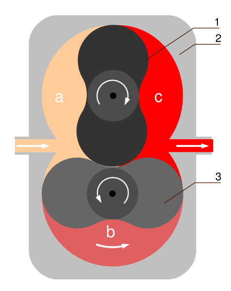 It is all the same technology. The only difference between vacuum folks and IC motor heads is the propulsion of the system. And as a matter of discussion, there is a 4 cylinder vacuum pump called "The Ecodry"  This is literally a four cylinder motor with an Electric motor used for propulsion......the four pistons move up and down just like a horizontally opposed Porsche or VW air cooled engine. Here is a vacuum Roots  |
||
Posted on: 2009/12/16 19:41
|
|||
|
Transfer
|
|
||
| flyboy | Re: 30 dollar 12HP+ air foil? | ||
|
Elite Guru

|
TPISpecialties is the inventor and patent holder of the Airfoil. Their book "Insider Hints" devotes four pages to the Airfoil. They claim a stock throttle body flows air at 668cfm. Put the Airfoil in and it flows 709cfm. Then again, there is that old saying about liars, damn liars and statisticians.
|
||
Posted on: 2009/12/17 1:07
|
|||
|
_________________
'91coupe, LT4Hotcam, some other stuff. If it's too loud, you're too old. "He works on old cars, then junks 'em" |
|||
|
Transfer
|
|
||
| bigmoe | Re: 30 dollar 12HP+ air foil? | ||
|
Senior Guru
|
Well I asked a simple question and got a 45 response reply/debate. All theory aside the only thing that would convince me either way is some dyno results. Anyone up for the test??
|
||
Posted on: 2009/12/17 1:19
|
|||
|
Transfer
|
|
||
| flyboy | Re: 30 dollar 12HP+ air foil? | ||
|
Elite Guru
|
See the above mentioned book. Take with grain of salt.
|
||
Posted on: 2009/12/17 2:50
|
|||
|
_________________
'91coupe, LT4Hotcam, some other stuff. If it's too loud, you're too old. "He works on old cars, then junks 'em" |
|||
|
Transfer
|
|
||
| CentralCoaster | Re: 30 dollar 12HP+ air foil? | ||
|
Senior Guru
|
Quote:
Those numbers sound reasonable to me. But as I mentioned earlier, the throttle body (at wot) isn't a very restrictive part of the system. So making it 10% more efficient doesn't translate into a measureable amount of horsepower. (And it won't increase flow by 10% through the system.) Plus your typical L98 is only pulling about 500 cfm to begin with. |
||
Posted on: 2009/12/17 5:11
|
|||
|
_________________
1985 Z51, ZF6 |
|||
|
Transfer
|
|
||
| CentralCoaster | Re: 30 dollar 12HP+ air foil? | ||
|
Senior Guru
|
Quote:
No, the PCV fresh air is in front of the throttle blades. Right between the throttle bores up top where the airfoil bolts in. (If it fed from the vacuum side, and the pcv enters the vacuum side, there'd be not much of a pressure difference, and no flow.) At wot, there isn't much manifold vacuum, so the PCV system doesn't flow much. All it's really doing then is allowing blowby to escape through the fresh air connection and through the pcv. If you block the fresh air vent, you will increase crankcase pressure slightly at WOT. |
||
Posted on: 2009/12/17 5:33
|
|||
|
_________________
1985 Z51, ZF6 |
|||
|
Transfer
|
|
||
You can view topic.
You cannot start a new topic.
You cannot reply to posts.
You cannot edit your posts.
You cannot delete your posts.
You cannot add new polls.
You cannot vote in polls.
You cannot attach files to posts.
You cannot post without approval.
|
|